


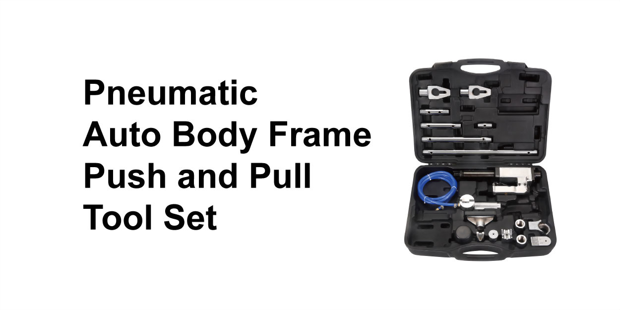
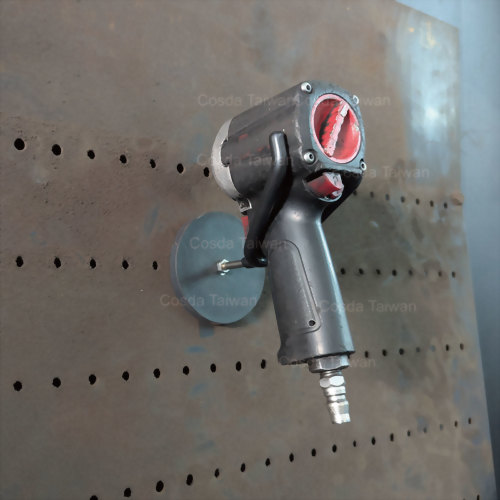
Pneumatic Auto Body Frame Push and Pull Tool Set
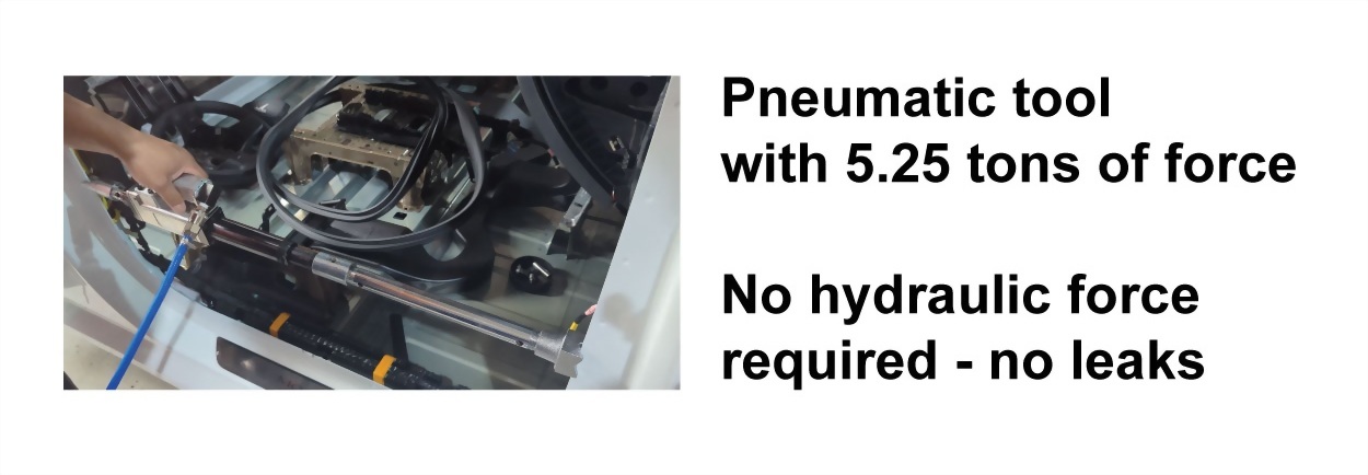
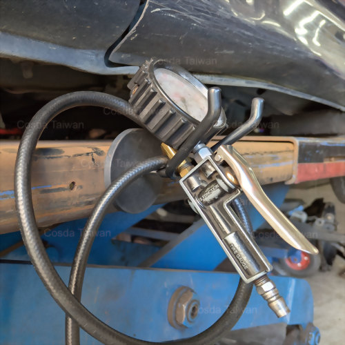
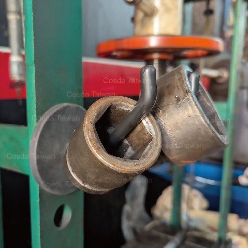
• Pneumatic tool features 5.25 tons of force. No hydraulic fluid is required and no unsafe and unpleasant leaks will occur
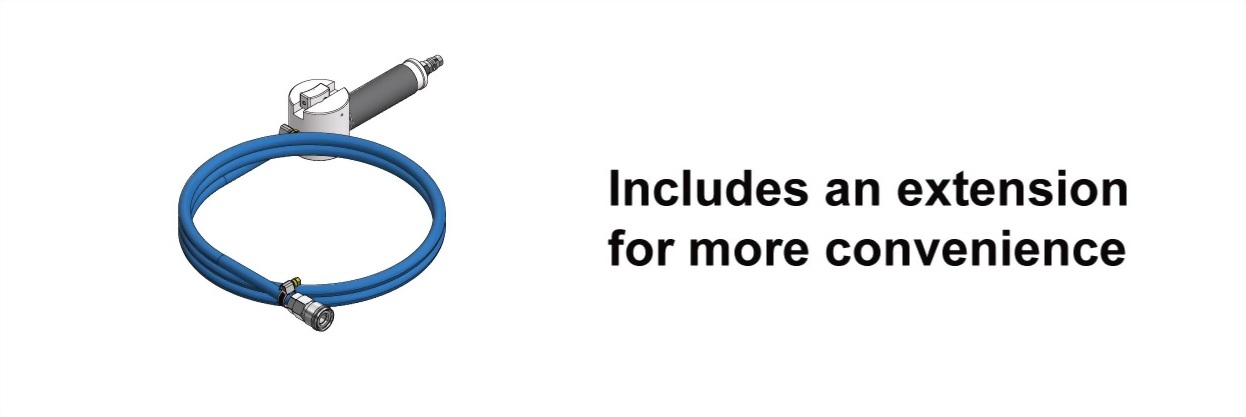
• Provided with a remote control with a 2 meter extension hose for extra safety
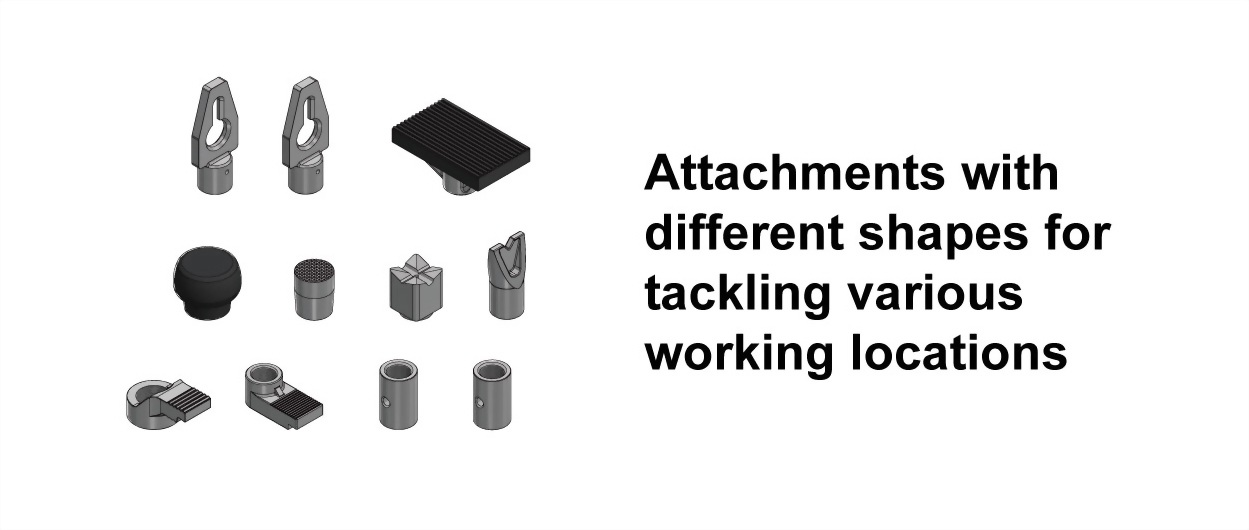
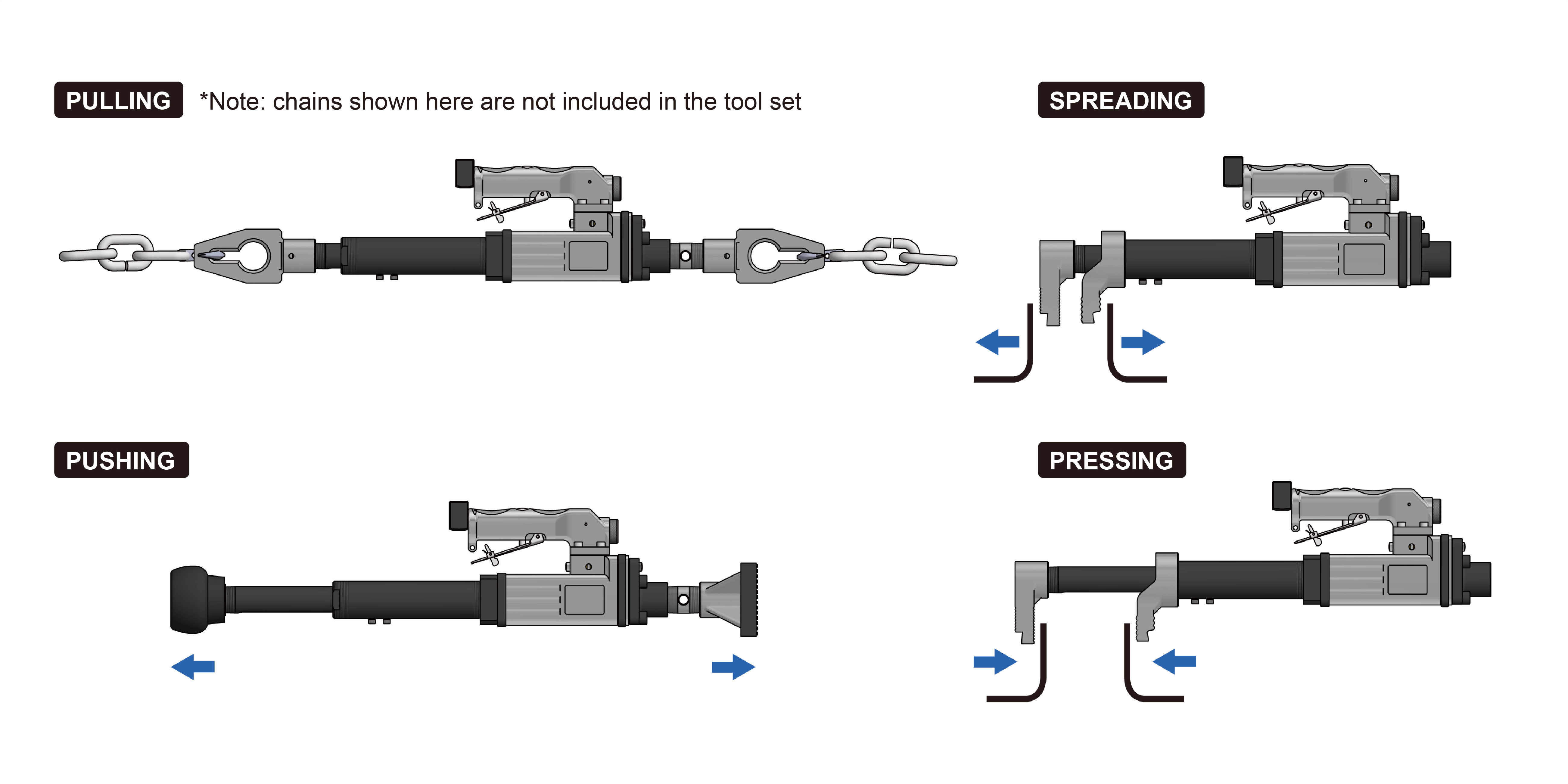
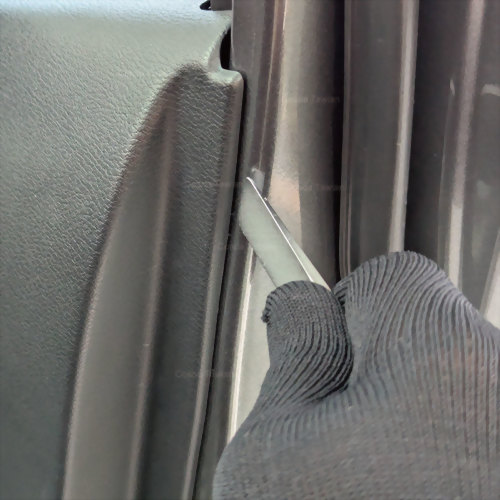
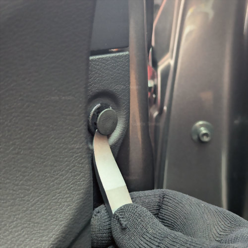
• Includes attachments for various auto body repair tasks, such as pushing / spreading and pulling / pressing
Key Features
1.Pneumatic
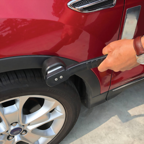
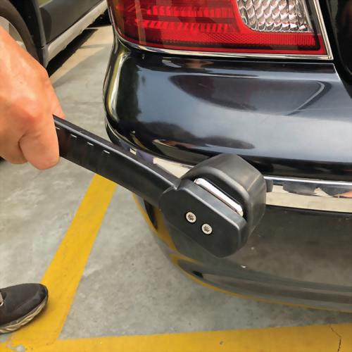
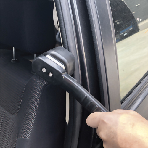
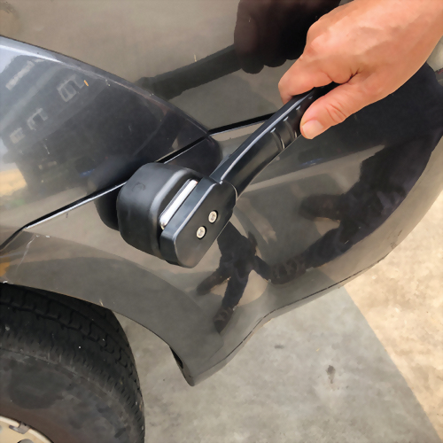
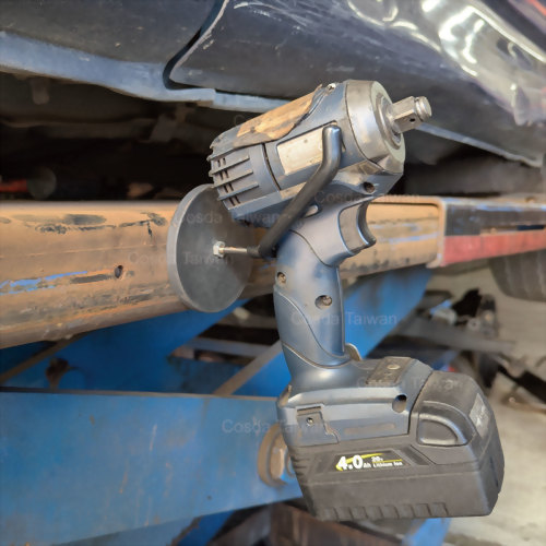
frame straightening—one set for push / pull / spread / press
Driven by a pneumatic tool and paired with multiple attachments, the SD-1196
supports common body and frame repair methods including pushing, spreading,
pulling, and pressing. Technicians can switch force direction quickly based
on the damage location, improving bay efficiency and repair flexibility.
2.5.25-ton
controlled force output for reliable alignment work
Delivers up to 5.25 tons of push/pull force—strong enough for most
structural correction tasks such as frame realignment, minor door frame/pillar
deformation, localized pulling, and spreading where both power and control
matter.
3.No
hydraulic fluid required—less mess and fewer shop-floor safety concerns
Unlike hydraulic systems
that require fluid and ongoing maintenance, this pneumatic design operates
without hydraulic oil, helping reduce leaks, cleanup time, and slip hazards,
keeping the work area cleaner and easier to manage.
4.2-meter
remote control hose—keeps the operator at a safer distance
Includes a 2-meter extension hose remote control, allowing the
technician to operate from a safer position and reducing hand exposure near
pinch points, compression zones, and potential rebound areas—enhancing overall
job-site safety.
5.Safer
pneumatic-work mindset—secure connections to reduce hose whip risk
Built for high-pressure air environments with an emphasis on secure hose and
fitting connections to help minimize accidental disconnection and hose-whip
risks—supporting professional shop safety expectations.
6.More
“deliverable” structural repairs—supports measurement / anchoring / pulling
workflow aligned with OEM standards
Structural repair is not just about force; it relies on a systematic process of
measurement, anchoring, and pulling strategy. When used within standardized
procedures and aligned with OEM repair manuals, the SD-1196 helps improve
consistency, reduce rework, and support quality outcomes.
Industry Background
The Engineering Reality Behind Automotive Frame Realignment
Automotive frame realignment is not a simple process of “bending metal back.” It is a structural correction procedure involving force control, material behavior, and load-path recovery within a complex vehicle body system.
Modern vehicle frames are composed of high-strength steels, multi-thickness reinforcements, and welded structural nodes. During a collision, deformation rarely occurs at a single visible point. Instead, impact energy travels through structural members, causing distributed distortion, including bending, stretching, torsion, and localized compression. What appears to be a misaligned section is often the result of force redistribution across multiple interconnected components.
This interconnected structure is the primary reason frame correction remains one of the most technically demanding procedures in body repair.
Material Behavior: Why Structural Steel Is Less Forgiving Than It Looks
Advanced High Strength Steel (AHSS) and other reinforced alloys are widely used in modern body structures to improve crash energy absorption. These materials provide high strength but operate within a narrow plastic deformation window.
When corrective force exceeds this range, the metal may appear visually restored while internal crystalline structures experience micro-fractures or stress concentration zones. These changes are not always visible during repair but may reduce long-term structural integrity and energy absorption performance in future impacts.
This makes force control more critical than force magnitude.
Load Path Complexity in Vehicle Structures
Vehicle frames function as load-distribution systems, not isolated beams. A pulling or pushing force applied in one area can influence geometry elsewhere. Incorrect force direction or sequencing may lead to:
- Dimensional correction in one section while inducing misalignment in another
- Altered suspension geometry due to structural shift
- Residual torsion that affects vehicle tracking stability
This phenomenon is known in structural mechanics as load path interaction, and it explains why repeated adjustments are common in traditional correction workflows.
Why Frame Correction Becomes Labor-Intensive
Frame restoration is essentially a process of controlled reverse deformation. Technicians must apply force gradually, reassess measurements, and repeat adjustments while preventing secondary structural damage. Each correction can influence multiple connection points, requiring continuous repositioning and recalibration.
Because of this, the process is:
- Mechanically demanding
- Time-consuming
- Highly dependent on operator experience
The challenge lies not in producing force, but in maintaining predictable, stable, and repeatable force application.
Structural Risk Factors in Traditional Frame Correction
Frame realignment involves several inherent engineering risks:
●Material Fatigue Risk – Excessive or poorly controlled force may introduce internal stress damage not immediately visible.
●Secondary Structural Damage – Incorrect anchoring or load points can damage unaffected areas, including weld seams and thin-gauge sections.
●Elastic Rebound Energy – Stored elastic energy may release suddenly if force is removed or anchoring fails, creating a high-energy hazard.
●Heat-Affected Zone Alteration – Improper heating or mechanical impact can alter metallurgical properties in high-strength steel components.
These risks are not theoretical; they stem from the physics of metal deformation and structural force transfer.
Industry Context
As vehicle structures evolve toward lighter materials, higher-strength alloys, and modular construction, the tolerance for uncontrolled force application continues to shrink. This structural evolution is driving the industry's ongoing search for more controlled and predictable force application methods, not as a trend, but as an engineering necessity.
Solutions
Solution 1 – Laser Marked Pneumatic Push and Pull Tools for Private Label Programs
Turn this pneumatic auto body and frame push and pull tool set into a laser marked body repair tool kit for automotive tool brands, private label programs, and distributors.
Key Benefits:
- Tool bodies can be laser marked with your logo, creating durable and professional branded pneumatic body and frame repair tools.
- Suitable for OEM automotive tool programs, private label body repair tools, and aftermarket collision repair tool lines.
Solution 2 – Local Air Fitting Customization for Pneumatic Body Repair Tools
Customize pneumatic air fittings to ensure compatibility with local workshop air systems and regional standards.
Key Benefits:
- Pneumatic connectors can be customized to match local air coupler standards (EU, US, JP, or other regional types).
- Improves compatibility with existing workshop air systems, reducing setup time and improving efficiency.
- Ideal for collision repair shops, body frame repair services, and professional automotive technicians.
Solution 3 – Branded Stickers for Pneumatic Body & Frame Repair Tool Sets
Enhance product identification and brand recognition with custom branded stickers for pneumatic body repair tool sets.
Key Benefits:
- Stickers can include your logo, product name, and key information for clear tool identification.
- Customers may provide their own sticker artwork, or we can assist with complimentary sticker design.
- Suitable for automotive tool distributors, private label programs, and aftermarket body repair tools.
Solution 4 – Packaging Options for Pneumatic Body Repair Tool Sets
Choose flexible packaging solutions to match different sales channels and brand positioning.
Key Benefits:
- Packaging options can include standard packaging or packaging with branded stickers.
- Suitable for e-commerce platforms, retail channels, and professional workshop tool kits.
- Helps brands present pneumatic body and frame repair tools in a clean, professional format.
Solution 5 – OEM & Multi-Market Pneumatic Body Repair Tool Solutions
Support OEM projects and multi-market distribution with adaptable customization and branding options.
Key Benefits:
- Laser marking, air fitting types, and sticker designs can be adjusted to meet different market requirements.
- Ideal for distributors and OEM customers serving multiple regions.
- Maintains a consistent core pneumatic tool structure while supporting global collision repair tool programs.
Q&A
Q1: What power source does it use? Does it require hydraulic fluid?
A: It is air-operated (pneumatic), and the manufacturer states no hydraulic fluid is required, eliminating concerns about hydraulic fluid leaks.
Q2: What is the maximum pushing/pulling force?
A: The pneumatic tool features 5.25 tons of pushing and pulling force.
Q3: Can it fully replace a full-size frame machine?
A: It is designed as a versatile push/pull/spread/press repair tool. For severe structural damage or repairs requiring precise measurement/alignment, professional frame equipment and measurement systems may still be necessary. (Operational recommendation)
Q4: What is the air inlet fitting/thread? Will it work with my shop quick coupler?
A: The air inlet thread/coupler type is not listed on the product page. To avoid mismatch, please confirm via the tool/manual, or share your coupler spec for verification.
Q5: Does it require maintenance or oiling? Since it’s not hydraulic, how do I maintain it?
A: It is designed with no hydraulic fluid required, reducing leak concerns. Keep the tool clean, prevent contamination at fittings/lines, and maintain your air system (filtering/moisture control/lubrication) per shop practice.
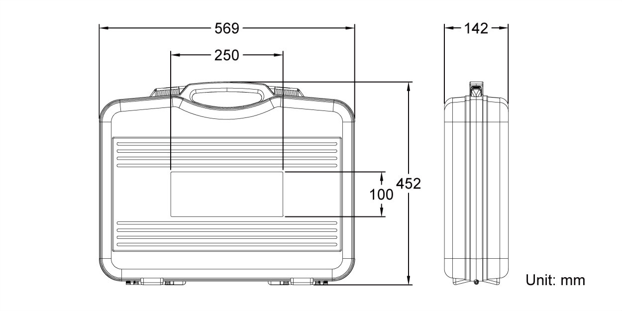
| Package | Blow molded case (black) | |
| Packing | 1 set in a master carton | |
| Weight per set | 16.6 kg | 36.5 lbs |
| Net weight per carton | 16.6 kg | 38.7 lbs |
| Gross weight per carton | 17.6 kg | 38.7 lbs |
| Size per set | 56.9 × 45.2 × 14.2 cm | 22.4 × 17.8 × 5.6 inch |
| Size per carton | 57.6 × 46.7 × 15 cm | 22.6 × 18.3 × 5.9 inch |
| Volume per carton | 0.04 CBM | 1.3 CUFT |
| Case label size | 24.8 × 9.8 cm | 9.7 × 3.8 inch |
| Suggested HS code |
82055990909 |
| MOQ with laser marking | 5 sets |
| MOQ without laser marking | 1 sets |
| Laser marking cost | + TWD 20 on the pneumatic body |
|
Not for sale in |
China |


")
